What Is a Heat Exchanger Tube and How Does It Work?
A Heat Exchanger Tube is a pressure-bearing passage that transfers thermal energy between two fluids without mixing them. It is widely used in boilers, condensers, refrigeration systems, oil refineries, and chemical plants. The tube may carry hot steam, cooling water, oil, or another process fluid. Its surrounding fluid absorbs or releases heat through the tube wall.
Frank P. Incropera, a respected heat-transfer educator, wrote, “A heat exchanger is a device used to transfer energy from a hot fluid to a cold fluid.” This simple statement explains the core purpose. However, real performance depends on more than temperature differences. Tube diameter, wall thickness, material conductivity, fluid velocity, and surface cleanliness all matter. A thin layer of scale can act like insulation. Small design details matter.
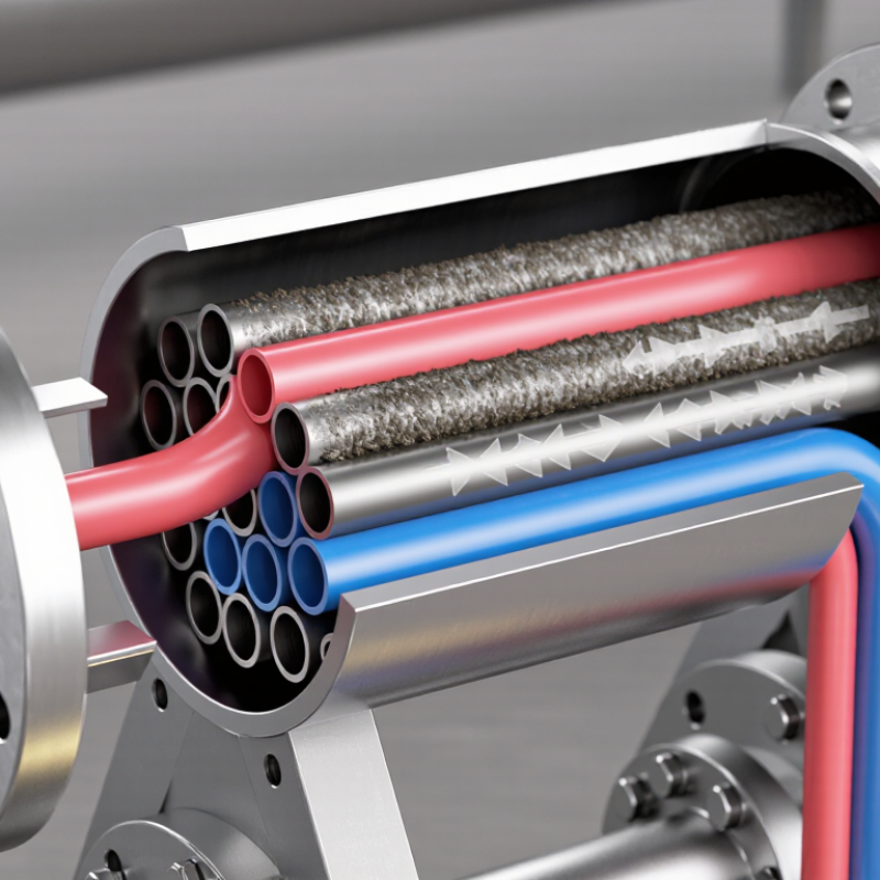
Inside a shell-and-tube exchanger, one fluid travels through multiple tubes while another flows around them. Heat moves by convection from the first fluid, conduction through the metal wall, and convection into the second fluid. Engineers monitor pressure, outlet temperature, vibration, and leakage during operation. These observations reveal problems before failure becomes serious. Not every tube performs equally. Fouling, corrosion, poor flow distribution, and thermal expansion can reduce efficiency over time. A reliable design therefore includes proper material selection, inspection access, and maintenance planning. Understanding these practical limits makes the term Heat Exchanger Tube more than a textbook definition; it becomes a critical part of safe, efficient thermal equipment.
What Is a Heat Exchanger Tube?
A heat exchanger tube is a hollow passage that transfers heat between two fluids without allowing them to mix. It is usually made from metal, such as stainless steel, copper alloys, or carbon steel. The tube wall acts as a controlled barrier. One fluid flows inside the tube, while another moves around its outer surface.
The working principle is simple. Heat travels from the hotter fluid through the tube wall and into the colder fluid. Thin walls improve heat transfer, but they may reduce strength and corrosion resistance. That trade-off matters. Engineers select tube diameter, wall thickness, length, and material according to temperature, pressure, flow rate, and fluid chemistry. In practical installations, hundreds of tubes may sit inside a shell, creating a large transfer area within limited space.
During maintenance, technicians inspect for pitting, scaling, vibration damage, and small leaks. Even a thin mineral layer can reduce performance by acting like insulation. Water quality and cleaning methods also affect service life. A tube may look sound externally but contain internal damage. That is why pressure testing, visual inspection, and suitable non-destructive testing are often combined. No tube design is perfect; efficiency, durability, cost, and cleanability must be balanced for the actual operating conditions.
How Heat Exchanger Tubes Transfer Thermal Energy
What Is a Heat Exchanger Tube and How Does It Work?
How Heat Exchanger Tubes Transfer Thermal Energy
A heat exchanger tube is a narrow passage that separates two moving fluids. One fluid flows inside the tube, while another travels around its outer surface. Heat moves from the warmer fluid to the cooler one without allowing them to mix. The wall stays solid. Thermal energy crosses three stages: convection from the hot fluid, conduction through the tube wall, and convection into the cooler fluid.
Flow direction matters. In counterflow operation, the fluids move in opposite directions, maintaining a stronger temperature difference along the tube. This arrangement often transfers more heat than parallel flow. Tube material, wall thickness, surface area, and fluid velocity also affect performance. A thin, conductive wall can reduce resistance, but excessive thinning may weaken the tube. Real engineering requires both thermal calculations and pressure checks.
During inspections, technicians may find scale, rust, or biological deposits inside the tubes. These layers act like insulation and reduce heat transfer. They can also narrow the flow path, increasing pressure loss. A clean design on paper may perform poorly after months of operation. This is where experience matters: temperature readings, flow measurements, vibration, and visual inspection should support the design model. Some assumptions will be wrong. Engineers must question them when field data disagrees. Small leaks can also contaminate the opposite fluid, so tube integrity deserves regular attention.
Key Components and Tube Configurations
A heat exchanger tube is a pressure boundary and a heat-transfer surface. It separates two fluids while allowing heat to pass through its metal wall. In a shell-and-tube exchanger, one fluid flows inside the tubes. The other travels across the tube bundle within the shell. Counter-current flow usually improves temperature recovery. Flow direction matters.
Key components include tubes, tube sheets, baffles, channels, pass partitions, gaskets, and the shell. Tube sheets hold each tube firmly and prevent fluid mixing. Baffles support long tubes and redirect shell-side flow. However, poorly spaced baffles can increase pressure loss and vibration. Tube diameter, wall thickness, pitch, and material affect performance. Field inspection often finds fouling near tube entrances, where velocity changes quickly.
Tube configurations create different maintenance choices. Fixed-tube-sheet designs are compact and economical, but shell-side cleaning can be difficult. U-tubes tolerate thermal expansion well and reduce stress at the tube sheets. Floating-head designs allow bundle removal, although they add sealing complexity. Single-pass tubes shorten the flow path. Multi-pass arrangements increase velocity and heat transfer, but they also raise pressure drop.
The International Energy Agency’s Energy Efficiency 2023 report states that industry consumed about 37% of global final energy. The U.S. Department of Energy’s Industrial Decarbonization Roadmap identifies process heating as roughly half of industrial energy demand.
These figures explain why small tube-layout decisions matter. A design is rarely perfect. Engineers must balance heat duty, cleaning access, vibration, cost, and service life.
Common Materials Used in Heat Exchanger Tubes
A heat exchanger tube is a narrow passage that carries one fluid while another fluid flows around it. Heat crosses the tube wall, but the fluids remain separated. In a shell-and-tube unit, hot process liquid may travel inside the tubes, while cooling water moves through the shell. Tube thickness, flow speed, and surface condition all influence heat transfer. Small deposits matter.
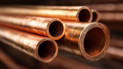
Carbon steel is economical and strong, but water containing oxygen or salts can cause corrosion. Stainless steel offers better resistance and suits many clean, moderately aggressive services. Copper alloys transfer heat efficiently and often perform well with seawater, though chemistry must be checked carefully. Titanium resists chloride attack and lasts in demanding cooling systems, yet its cost can limit use. Nickel alloys handle severe temperatures and chemicals, but fabrication and inspection become more demanding.
Material selection is not simply a conductivity contest. Engineers compare pressure, temperature, chloride level, vibration, erosion, fouling, and maintenance access. A polished tube may reduce deposits, but it cannot correct unsuitable water chemistry. During inspection, technicians look for pitting, wall thinning, and leaking joints, often using ultrasonic measurements. No material wins every service. A first choice can still be wrong after operating data arrives. That is why fluid sampling and real duty conditions should guide final tube selection.